What is Unified Architecture Process (UAP)

The UAP is a comprehensive, production-ready methodology designed to enable the cost-effective development of high-quality software architectures. It offers a structured framework that covers all key architectural design activities and provides clear, step-by-step guidance for their implementation.
UAP was developed to address recurring challenges faced by software designers and architects, including:
- How to design software architecture systematically, with clear step-by-step guidance.
- Where to find concrete, detailed guidelines for each architectural design activity.
- How to effectively design for non-functional requirements, which are often complex and difficult to formalize.
- What strategies support robust architectural design for large-scale, highly complex systems.
- Whether a standardized template exists for documenting architecture descriptions with clarity and minimal effort.
To address these challenges, the UAP employs the following key strategies:
- Systematic Design Process
A structured process model that organizes architectural design into well-defined activities, each with clear procedural steps. - Detailed Design Guidelines
Comprehensive, implementation-level guidance for each activity, supported by validation checklists to ensure completeness and correctness. - Design for Non-Functional Requirements
A dedicated activity—A5. Design for Non-Functional Requirements—focused on addressing critical quality attributes such as performance, security, and modifiability. - Support for Complex Systems
Tailored methodologies and best practices that enable effective architectural design for large-scale, highly complex systems. - Standardized Documentation Template
A fully aligned architecture description template that promotes efficient, consistent, and clear documentation.
Evolution of UAP
The UAP is the product of more than two decades of academic research in software engineering, combined with extensive hands-on experience designing large-scale systems for government and industry. It is both theoretically rigorous and firmly rooted in proven software engineering principles and practices. Over time, UAP has been applied to diverse real-world systems, including management information systems, enterprise platforms, cloud services, mobile and embedded applications, real-time and autonomous systems, machine learning solutions, and platform software.
Its evolution has been shaped by close collaboration between academia and industry. Software architects, senior developers from leading IT corporations, and computer science faculty have all contributed to its refinement. Their iterative feedback and project-driven insights have been instrumental in continuously advancing UAP into a practical, production-ready methodology.
Underlying Technologies of UAP
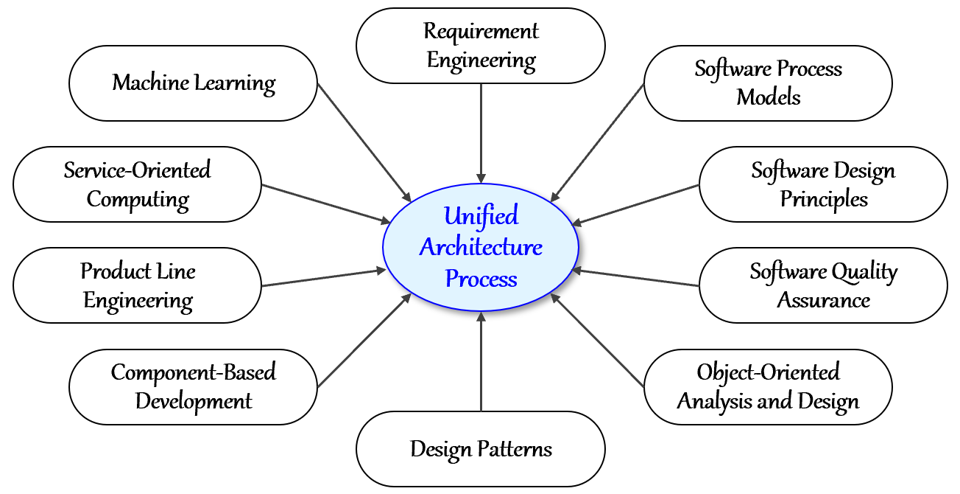
The UAP is grounded in a set of foundational technologies that provide the methodological and technical backbone for software architecture. Each contributes unique strengths that, when combined, enhance the effectiveness, precision, and reliability of the architectural design process. The core technologies underlying the process are illustrated in the figure.

Process Model of UAP
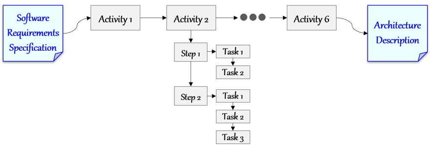
The Unified Architecture Process consists of a structured process model supported by detailed instructions for carrying out architectural design activities. This process model is organized into three hierarchical work units: Activity, Step, and Task.
- Activity
A high-level unit of work representing a major phase of the architecture design process. Each activity defines clear objectives and is composed of multiple steps. - Step
A structured subunit within an activity that outlines the procedures or actions needed to move the activity forward. Each step is carried out through a sequence of tasks. - Task
The most detailed unit of work, representing concrete actions or operations required to complete a step.

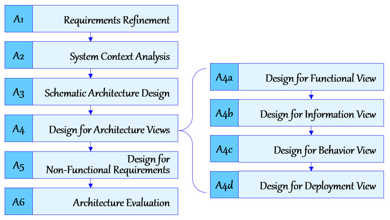
The UAP is organized into six major design activities, presented in sequence as shown in the figure.

Each activity represents a distinct phase of the architectural design process, moving from requirements refinement to architecture evaluation. In particular, Activity A4: Design for Architecture Views is divided into four sub-activities, each focused on a specific view: functional, information, behavior, and deployment.
Activity A1. Requirements Refinement
This activity ensures that stakeholder requirements are clarified and corrected before architectural design begins. Since initial requirements often contain gaps or ambiguities that can cause defects in later models, refining them thoroughly is essential for sound architectural decisions. The activity is organized into steps.
- Step 1. Identify Stakeholders
Identify the system’s stakeholders to ensure the architecture reflects their expectations. Engaging them early supports informed and comprehensive design decisions. - Step 2. Refine Functional Requirements
Refine the system’s functional requirements using requirement engineering principles and techniques. - Step 3. Refine Non-Functional Requirements
Refine the system’s non-functional requirements using requirement engineering principles and techniques.
Activity A2. System Context Analysis
This activity constructs a context model of the system based on the refined requirements. A context model offers a high-level view of system boundaries, functionality, data, and behavior. It is particularly valuable for architects unfamiliar with the target system, as it clarifies scope, features, and interactions. The activity is organized into steps.
- Step 1. Analyze Boundary Context
Analyze the system’s boundary context using a Data Flow Diagram (DFD) to clarify external interactions and system scope. - Step 2. Analyze Functional Context
Analyze the system’s functional context using a use case diagram to capture interactions and functionalities. - Step 3. Analyze Information Context
Analyze the system’s information context using a class diagram to represent data and relationships. - Step 4. Analyze Behavior Context
Analyze the system’s behavior context using an activity diagram to model processes and workflows.
Activity A3. Schematic Architecture Design
This activity designs the schematic architecture of the system by integrating appropriate architecture styles. The schematic architecture provides a stable and enduring structural layout that underpins subsequent architectural decisions. The activity is organized into steps.
- Step 1. Identify candidate architecture styles
Identify architecture styles suitable for designing the schematic architecture. - Step 2. Evaluate candidate architecture styles
Evaluate candidate architecture styles to determine their suitability for the target system. - Step 3. Integrate architecture styles
Incorporate the selected architecture styles into the schematic architecture of the target system. - Step 4. Refine schematic architecture
Refine the schematic architecture by making additions and modifications to ensure it fully meets system requirements.
Activity A4. Design for Architecture Views
This activity focuses on designing the architecture from multiple architectural perspectives, recognizing that architecture design inherently involves distinct views. Accordingly, this activity is subdivided into the following view-specific design activities:
- Activity 4a. Design for Functional View
- Activity 4b. Design for Information View
- Activity 4c. Design for Behavior View
- Activity 4c. Design for Deployment View
Activity A4a. Design for Functional View
This activity designs the architecture for the functional view of the system. The functional view models functionality by defining components and interfaces and allocating them within the schematic architecture. The activity is organized into steps.
- Step 1. Refine use case model
Refine the context-level use case diagram and provide detailed descriptions for use cases with complex functionality. - Step 2. Define functional components
Define the system’s functional components based on the use case diagram and the principles of the selected architecture style. - Step 3. Allocate functional components
Allocate functional components to their designated placeholders within the schematic architecture. - Step 4. Define functional component interfaces
Specify the interfaces of functional components by defining the services they provide and require. - Step 5. Design for functional variability
Model variability in functional components and design them to support flexible configurations while maintaining system integrity.
Activity A4b. Design for Information View
This activity designs the architecture for the information view, addressing persistent datasets, data components, their relationships, and their allocation within the schematic architecture. The activity is organized into steps.
- Step 1. Refine persistent object model
Produce a well-defined persistent object model by refining and enhancing the context-level object model. - Step 2. Define data components
Derive data components from the refined class diagram, grouping related classes into cohesive units. - Step 3. Allocate data components
Assign data components to their designated placeholders within the schematic architecture. - Step 4. Define data component interfaces
Specify the interfaces of selected data components, defining the operations for accessing and manipulating persistent data. - Step 5. Design object persistence
Design object persistence mechanisms to manage the storage and retrieval of data components.
Activity A4c. Design for Behavior View
This activity focuses on designing the architecture for the behavior view, which primarily addresses the system’s runtime behavior and the detailed control flows of complex functional elements. The activity is organized into steps.
- Step 1. Refine system control flow
Refine the context-level system control flow with detailed observations on runtime behavior. - Step 2. Identify key behavioral elements
Identify key behavioral elements and specify appropriate behavior representation schemes. - Step 3. Define detailed control flows
Represent detailed control flows for selected behavioral elements using designated schemes and ensure alignment with other architectural views.
Activity A4d. Design for Deployment View
This activity designs the architecture for the deployment view, addressing computing nodes, execution environments, network connectivity, and the allocation of software artifacts to nodes. The activity is organized into steps.
- Step 1. Define computing device nodes
Specify the hardware configuration of computing device nodes for the target system. - Step 2. Define execution environments
Specify the execution environment of each computing device node in the system. - Step 3. Define network connectivity
Define network connectivity among nodes through communication paths and network configurations. - Step 4. Allocate software artifacts
Allocate software artifacts onto the identified execution environment nodes in the deployment diagram.
Activity A5. Design for non-functional requirements
This activity designs the architecture to address the non-functional requirements of the system by augmenting the view-based design with architectural tactics that fulfill the identified requirements. The activity is organized into steps.
- Step 1. Identify facts and policies
Identify the facts and policies that underlie non-functional requirements, forming the foundation for architectural tactics. - Step 2. Define criteria for tactics
Define criteria for deriving architectural tactics based on the identified facts and policies. - Step 3. Define candidate tactics
Define candidate architectural tactics that address the targeted non-functional requirements. - Step 4. Evaluate candidate tactics
Evaluate candidate architectural tactics by analyzing costs, benefits, and applicability, and select the most appropriate ones. - Step 5. Integrate selected tactics
Integrate the selected architectural tactics into the view-based design, ensuring consistency with architectural views. - Step 6. Validate conformance
Validate the conformance of intermediate artifacts to their preceding artifacts using a conformance map.
Activity A6. Architecture Evaluation
This activity evaluates the architecture design of the system to identify risks, issues, drawbacks, and areas for improvement, ensuring alignment with functional and non-functional requirements. The activity is organized into steps.
- Step 1. Identify target elements for evaluation
Identify the specific design elements in the architecture that require evaluation based on importance, complexity, or risk. - Step 2. Define architecture evaluation methods
Select appropriate approaches and methods for evaluating the identified design elements. - Step 3. Apply architecture evaluation methods
Apply the selected evaluation methods to assess the architecture and identify risks, issues, and areas for improvement.
Reproduced from Hands-on Software Architecture: Unified Architecture Process, Springer, 2025.
