
Software Architecture · ART-SA-04
Introducing the Unified Architecture Process
Making Software Architecture Design Systematic, Repeatable, and Traceable
Software architecture design is among the most consequential activities in software engineering. Architectural decisions fix the fundamental organization of a system and, through it, shape functionality, quality attributes, implementation effort, operational behavior, and long-term evolvability. Yet architecture design is still frequently conducted as an implicit, experience-dependent practice in which the resulting design reflects the individual judgment of the architect more than an explicit engineering procedure. Under such conditions, significant concerns may be overlooked, design decisions become difficult to justify, reproduce, or audit, and architectural quality varies considerably across teams and projects.
An earlier article in this series, ART-SA-02, argued that architecture design benefits substantially from a methodological approach that makes design work explicit, structured, and repeatable. This article introduces a concrete methodology of that kind, the Unified Architecture Process (UAP) [1], which combines a hierarchical process model with detailed design instructions. Its central aim is to confer three properties on architecture design:
- Systematic. Architecture design proceeds through a complete, well-defined, and principled sequence of design work.
- Repeatable. Different architects applying the methodology to comparable problems follow comparable procedures and attain comparable quality.
- Traceable. Each architectural decision can be followed back to the requirements that motivated it and forward to the design elements and evaluation results that realize and validate it.
1. Background of UAP
UAP is a production-oriented methodology intended to support the cost-effective development of high-quality software architectures. It addresses both functional and non-functional requirements and spans the full scope of architecture design, from the refinement of stakeholder requirements to the evaluation of the resulting architecture.
Motivation for UAP
UAP was motivated by recurring questions raised by software architects and designers in practice:
- How can architecture be designed systematically, with the procedural clarity of a cookbook?
- Where can concrete guidelines for executing each design activity be found?
- How can non-functional requirements, which are often intricate and difficult to formalize, be addressed rigorously at the architectural level?
- How can architectural complexity be managed in large-scale systems?
- How can an architecture be documented completely without excessive effort?
UAP responds to these questions through corresponding design strategies: a structured process model, detailed activity-specific guidelines with validation checklists, a dedicated activity for non-functional requirements, methods tailored to complex systems, and a standardized architecture description template aligned with the process.
Evolution of UAP
UAP is the result of more than two decades of sustained development that has combined academic research in software engineering with industrial practice. It was developed by a team of established software engineering researchers led by Dr. Soo Dong Kim. The team’s academic research shaped the methodological foundation of UAP. Its practical experience in designing large-scale systems for government and industry shaped the methodology’s practical orientation.
UAP has been applied in industry for approximately twenty years. At several major IT corporations, it has been taught to engineers and used to guide architecture design in industrial projects across a variety of application domains. It has also served as a basis for software architecture education at universities. Feedback from industrial architects, senior developers, and academic faculty in these settings has continuously informed its refinement.
The range of systems to which UAP has been applied has broadened over this period, and the methodology has been refined accordingly. The publication of Hands-on Software Architecture: Unified Architecture Process [1] in 2025 consolidated this body of work into a complete and documented methodology, and its ongoing extension addresses the architecture of LLM-based, agent-based, and physical AI systems.
Underlying Technologies
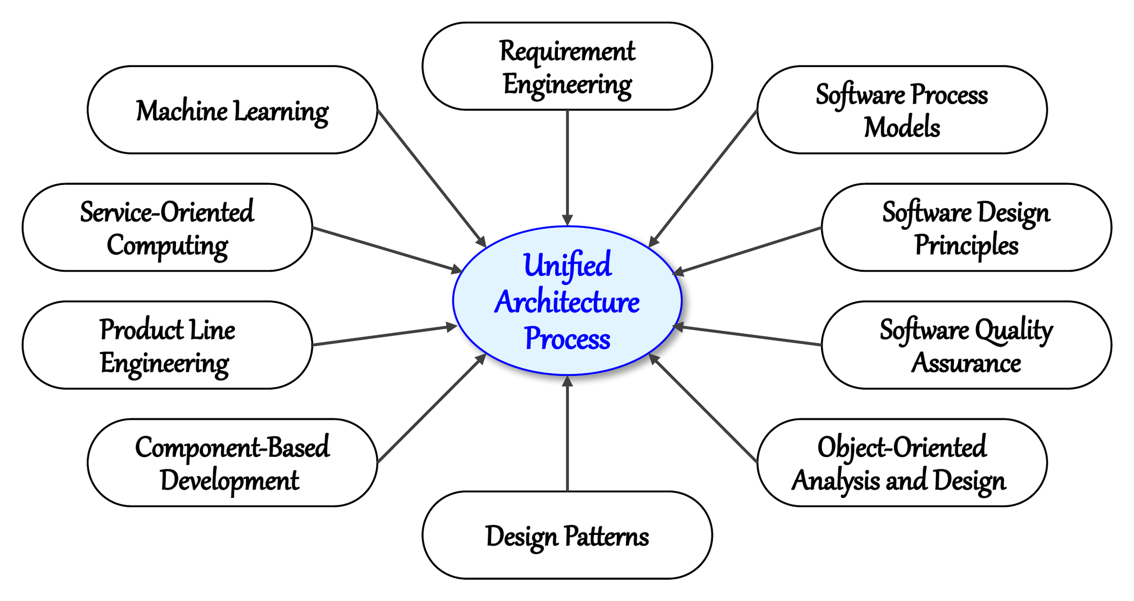
UAP draws on a broad set of foundational disciplines, including requirements engineering; software process models; fundamental design principles such as abstraction, modularity, separation of concerns, and the SOLID principles; software quality assurance; object-oriented analysis and design with UML; design patterns; component-based development; product line engineering; service-oriented computing; and machine learning as a tactical means of addressing intelligence requirements. Figure 1 shows the relationship between UAP and these disciplines. Each discipline contributes specific principles or methods that UAP integrates into its process model and instructions.
Position Among Established Approaches
UAP builds on, rather than replaces, the established body of software architecture knowledge. ISO/IEC/IEEE 42010 [2] defines the conceptual elements of architecture descriptions, including stakeholders, concerns, viewpoints, views, and rationale, but deliberately does not prescribe a design process. Views and Beyond [3] defines how architectures should be represented and documented, Attribute-Driven Design (ADD) addresses quality-attribute-driven design decisions, and the Architecture Tradeoff Analysis Method (ATAM) provides a structured approach to architecture evaluation [4]. Each addresses an important but partial aspect of architectural work. UAP integrates the corresponding concerns, namely requirements refinement, context analysis, style-based structural design, multi-view design, quality-driven tactic derivation, and evaluation, into a single, prescriptive, end-to-end design process.
2. Organization of UAP
In keeping with the general notion of a methodology, UAP consists of two complementary elements: (1) a process model that prescribes the sequence of design work, and (2) a set of instructions that specify how each unit of that work is to be performed. Both are grounded in a knowledge base of established software engineering principles, methods, and practices.
Hierarchical Work Units
UAP organizes architecture design into three levels of work units, as shown in Figure 2.
- Activity. A major phase of the design process with a cohesive design objective.
- Step. A structured subunit of an activity that specifies the procedure required to advance it.
- Task. The most granular unit, a concrete action that contributes to completing a step.
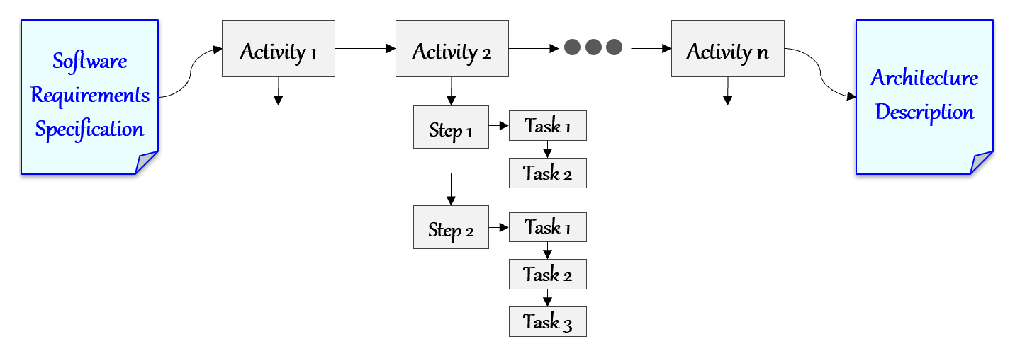
This decomposition applies the divide-and-conquer principle to architecture design, transforming an otherwise overwhelming design problem into a set of focused and manageable units of work.
Activities and Steps
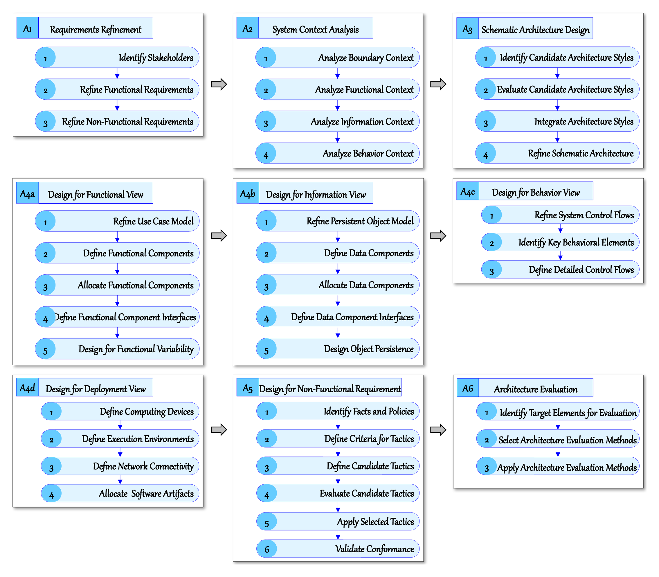
The process model defines six major activities that together span the full scope of architecture design, from initial requirements to a validated architecture. Activity A4, Design for Architecture Views, is decomposed into four view-specific sub-activities, so that the process comprises nine activity units and a total of 37 steps. Table 1 summarizes the objective of each activity.
Table 1. Activities of UAP
| Activity | Objective |
|---|---|
| A1. Requirements Refinement | Refine initial stakeholder requirements so that their deficiencies do not propagate into design models as defects. |
| A2. System Context Analysis | Construct a context model of the system’s boundary, functionality, information, and behavior before structural decisions are made. |
| A3. Schematic Architecture Design | Produce the stable, enduring structural layout of the system in terms of tiers, layers, components, and their relationships by integrating appropriate architecture styles. |
| A4a. Design for Functional View | Define functional components and their interfaces and allocate them within the schematic architecture. |
| A4b. Design for Information View | Define data components for persistent datasets, allocate them within the schematic architecture, and design their persistence. |
| A4c. Design for Behavior View | Define the runtime control flows of the system and the detailed control flows of behaviorally complex elements. |
| A4d. Design for Deployment View | Define computing nodes, execution environments, and network connectivity, and allocate software artifacts to the nodes. |
| A5. Design for Non-Functional Requirements | Address quality attributes through architectural tactics derived from refined non-functional requirements and integrated into the views. |
| A6. Architecture Evaluation | Assess the design for adequacy, consistency, and feasibility, and refine it before implementation. |
The activities are performed in the sequence shown in Figure 3, which presents the process chart of UAP together with the steps that compose each activity. Each activity takes the outputs of its predecessors as input. The refined requirements from A1 and the context model from A2 form the basis for the schematic architecture produced in A3, which, together with the refined requirements, serves as the structural baseline for the four view-specific sub-activities of A4. A5 then strengthens the view-based design with architectural tactics, and A6 evaluates the resulting architecture. Within each activity, the steps are likewise ordered so that the results of each step inform the next, and each step is further decomposed into tasks that are specified in its instruction.
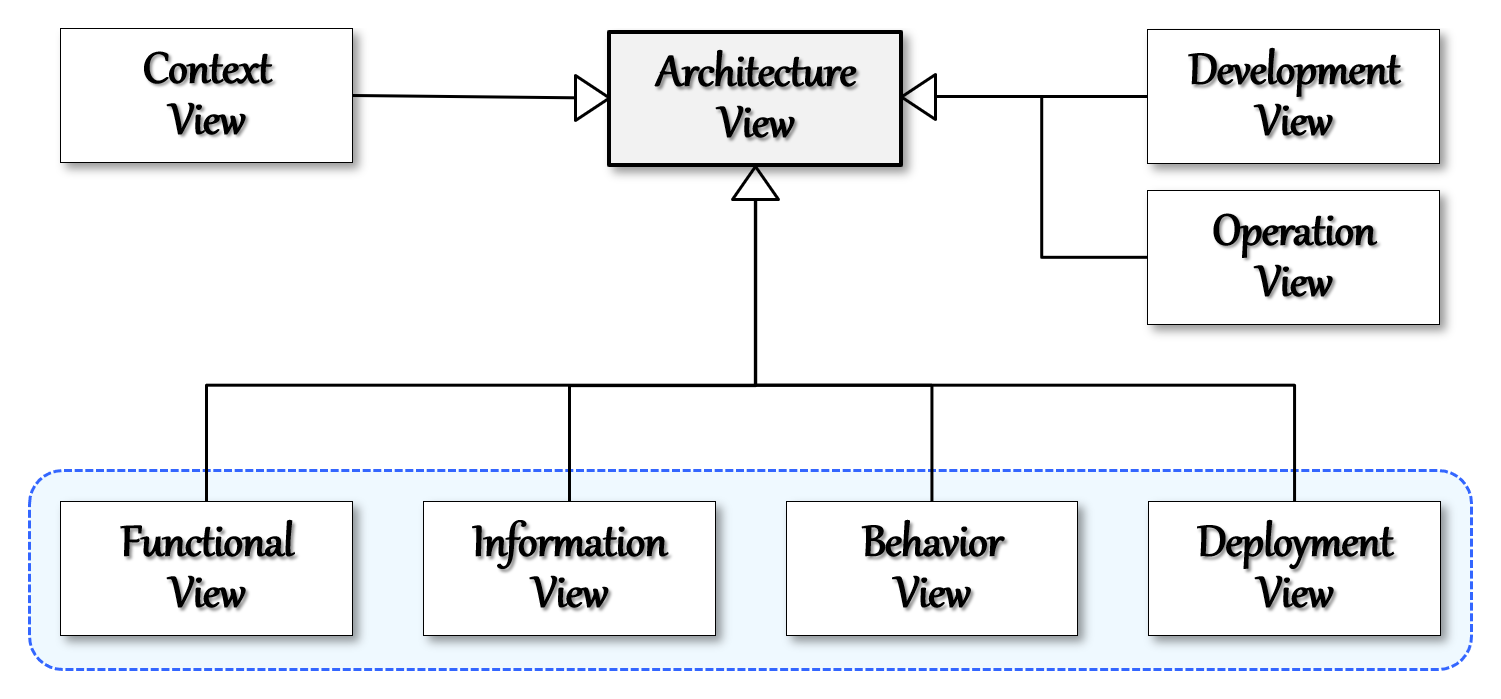
Activity A4 addresses the four views that UAP regards as essential for a wide range of systems, namely the functional, information, behavior, and deployment views. They belong to the seven architecture views defined in UAP, shown in Figure 4: the context view is produced in A2, and the development and operation views may be added according to the needs, scale, and complexity of the project. View-specific design is driven by the refined requirements, takes the schematic architecture produced in A3 as input, and adds the design decisions specific to each view. Because functional components, data components, and software artifacts are allocated to locations within the schematic architecture, the views elaborate a single, coherent structure and remain mutually consistent. Likewise, dedicating a full activity to non-functional requirements ensures that quality attributes receive explicit, methodical treatment rather than being left to implicit judgment or deferred to implementation.
Instructions and Checklists
Each step in UAP is accompanied by an instruction that provides detailed methods, best practices, and illustrative examples. The instructions are developed according to three criteria:
- Logical Sequencing of Tasks. Each step is decomposed into tasks arranged in an order that reflects their logical dependencies.
- Specificity. Guidance is stated with sufficient precision, supported by figures, diagrams, tables, and examples, to minimize ambiguity in interpretation.
- Consistency. Terminology, notation, and method are uniform across all activities, steps, and tasks, reducing errors and supporting collaborative work.
Each activity is further accompanied by a checklist capturing its critical design aspects and the applicable best practices, 245 items in total across the 37 steps. The checklists give architects and reviewers a common, explicit basis for verifying the outcome of every activity, rather than leaving adequacy to reviewer-specific judgment. Together, the instructions and checklists are the principal source of repeatability: they capture design knowledge in a form that can be learned, applied, reviewed, and transferred across teams and organizations.
Tailoring
Not every activity is necessary for every project. UAP defines explicit criteria under which individual activities may be omitted, for instance when requirements are already well defined and thoroughly validated, when the system context mirrors well-understood prior projects, or when a system is small enough that a separate schematic design would constitute unnecessary overhead. When A3 is omitted because the system structure has already been established and validated, that existing structure serves as the baseline to which view elements are allocated. Because the tailoring decision is itself governed by stated criteria, the process scales down in a principled rather than ad hoc manner and remains repeatable across systems of widely varying size and complexity.
Traceability Across Activities
The ordering of the activities establishes an explicit chain of derivation. Refined requirements (A1) inform the system context model (A2); the context model informs the selection and integration of architecture styles (A3); view-specific design (A4), driven by the refined requirements, elaborates the schematic architecture; architectural tactics (A5) are derived from refined non-functional requirements; and evaluation (A6) examines the resulting design against those requirements. Within A5, each non-functional requirement is refined in terms of its underlying facts and policies, criteria for tactics are defined from that refinement, and candidate tactics are evaluated before a justified subset is selected and integrated. The rationale for each design decision is therefore recorded as part of the design procedure rather than reconstructed afterward.
3. Applicability of UAP to Various Domains
UAP is a domain-independent methodology. Its activities, steps, and tasks address concerns common to software systems in general, while the characteristics of a particular domain are accommodated at three points in the process: the selection and integration of architecture styles in A3, which begins with determining the inherent types of the target system; the relative emphasis placed on the architectural views in A4; and the architectural tactics derived for the dominant quality attributes of the domain in A5. Process tailoring then adjusts the set of activities to the project context. The following domains illustrate this adaptation.
- Management Information and Enterprise Systems. The functional and information views carry most of the design weight, tiered and layered styles typically shape the schematic architecture, and tactics address security, data integrity, and modifiability.
- Embedded and Real-Time Systems. The behavior view captures control flows and event handling with precision, the deployment view binds software artifacts to processing units, and tactics address latency, determinism, reliability, and safety. The book illustrates tailoring for an automotive adaptive cruise control system that integrates deep learning models, in which an established reference architecture allows A3 and A4d to be omitted while A5 remains essential.
- Mobile Systems. The schematic architecture separates device-side and server-side tiers, the information view addresses local data and synchronization, and tactics address responsiveness, energy efficiency, offline operation, and the protection of data held on the device.
- Cloud-Based Systems. Service-oriented and microservice styles commonly shape the schematic architecture, the deployment view defines nodes, execution environments, and network connectivity in the cloud infrastructure, and tactics address scalability, availability, and elasticity. The book illustrates tailoring for the enhancement of a global cloud-based system, in which A1 and A2 are omitted while A3 through A6 are retained.
- Platform Software. Product line engineering and the open-closed principle, applied through the Design for Functional Variability step of A4a, support the definition of variation points that allow the platform to be customized for individual products.
- Conventional Machine Learning Systems. UAP treats machine learning as a tactical means of addressing intelligence requirements. Model inference, training pipelines, and the associated data are designed as components within the views, and A5 addresses prediction accuracy, explainability, and the computational cost of inference. The authors have applied UAP extensively to machine learning-based medical diagnosis and treatment systems.
- LLM-Based Systems. The language model is treated as an external or hosted component whose interfaces, data flows, and deployment are designed in the views. A5 derives tactics for prompt and context management, response quality, latency, cost, and the control of non-deterministic outputs.
- Agent-Based Systems. UAP identifies agent-specific considerations within each activity, including the orchestration of agents, the boundaries of agent autonomy, context and memory management, and governance with human oversight. It also introduces a proposed Intelligence View that complements the existing views; this extension will be examined in subsequent articles.
- Physical AI Systems. The behavior view models the cycles of perception, decision, and actuation, the deployment view distributes computation between edge devices and the cloud, and tactics address safety, fault tolerance, and real-time responsiveness.
Across these domains, the process remains the same; what varies is the content of the decisions made within it. This separation allows an organization to adopt a single methodology across product lines and technology generations while still producing architectures suited to each domain.
4. Benefits of Applying UAP
The benefits of applying UAP follow from its process model, instructions, and checklists, and they accrue at two levels: the architecture produced, and the projects and organizations that apply the methodology.
Benefits for the Architecture
- Higher Design Quality. Because the process covers every essential design concern, from requirements refinement to evaluation, significant concerns are less likely to be overlooked, and design flaws are identified in A6 before they propagate into implementation.
- Explicit Treatment of Non-Functional Requirements. A dedicated activity derives architectural tactics from refined non-functional requirements, so that quality attributes such as performance, scalability, reliability, and security are designed into the architecture rather than addressed late in development.
- Consistent Views. Allocating functional components, data components, and software artifacts within a common schematic architecture keeps the architectural views mutually consistent.
- Justifiable Decisions. The rationale for each decision is recorded as part of the design procedure, which supports design reviews, change impact analysis, and audits in regulated and safety-critical domains.
Benefits for Projects and Organizations
- Managed Complexity. The decomposition of design work into activities, steps, and tasks, together with abstraction and separation of concerns, makes the architecture of large-scale and complex systems tractable.
- Higher Productivity. A step-by-step roadmap reduces rework and decision-making overhead, and reusable best practices embedded in the instructions shorten the time required for each design step.
- Right-Sized Process. Principled tailoring and domain independence allow the same methodology to be applied to small and large systems and across application domains without unnecessary overhead.
- Consistent Quality Across Teams. Explicit instructions and checklists reduce the dependence of architectural quality on the individual expertise of the architect, so that comparable projects produce architectures of comparable quality.
- Effective Communication. Uniform terminology, notation, and document structure give architects, developers, reviewers, and other stakeholders a shared basis for discussing and assessing architectures.
- Transferable Design Knowledge. Design knowledge captured in the instructions and checklists can be taught, applied, and transferred across teams, which supports the training of architects and the onboarding of new team members, as demonstrated by its long-standing use in architect training at major IT corporations.
5. Resources for UAP
UAP Book
The primary and definitive guide to UAP is Hands-on Software Architecture: Unified Architecture Process (Springer, 2025). The book presents the complete methodology, including the process model, step-level instructions, and checklists.
Resource Website
The companion website, handsonse.org (Hands-on Software Engineering), supplements the book with resources for learning and applying UAP. Its Software Architecture section introduces the methodology, supports its application in practice, and illustrates it with case studies. Step-level instructions and detailed method descriptions remain in the book. The section is organized into the pages described below, and further resources will be added over time.
- Software Architecture Basics. An introduction to the definition, core elements, and importance of software architecture. It also covers the roles of the architect and the challenges of architecture design that motivate a systematic methodology.
- UAP Overview. An overview of the methodology, its underlying technologies, work units, and activities. It serves as the entry point to the other pages.
- UAP Practitioner Guides. A guide organized by the six UAP activities. It summarizes the steps and tasks of each activity for practitioners applying the process.
- UAP Templates and Checklists. Architecture description templates aligned with the activities, steps, and tasks of UAP, offered in variants suited to projects of differing scale and complexity, together with summaries of the activity checklists presented in the book.
- UAP Design Reference. Downloadable quick references, such as an overview flyer, a reference guide, and process charts, that summarize the activities, steps, and tasks of UAP in a compact form for use during design.
- UAP Case Studies. Case studies that apply UAP from start to finish across various application domains, from conventional information systems to AI-based systems. Each case study presents a system’s requirements specification and the resulting architecture description, showing how the methodology is applied in practice.
- Software Architecture Blog. Articles that examine specific issues, common misconceptions, and practical extensions related to UAP. Topics include the scope of software architecture, the need for a design methodology, architectural drivers, and architecture for AI-based systems.
6. Conclusion
Architecture design determines much of a system’s quality and long-term cost, yet it too often depends on implicit practice and individual expertise. UAP addresses this problem with a methodology developed through more than two decades of research and industrial application. Its process model of six activities and 37 steps, together with detailed instructions, activity checklists, and principled tailoring criteria, makes architecture design systematic, repeatable, and traceable. Domain characteristics are handled through style selection, view emphasis, and tactic derivation, not through changes to the process. As a result, the same methodology applies to systems ranging from enterprise information systems to embedded, cloud, machine learning, LLM-based, agent-based, and physical AI systems.
Applying UAP improves the quality of individual architectures. It also makes architectural practice more consistent and easier to transfer across projects and organizations. The companion resources on handsonse.org support adoption, from initial assessment to full application. Subsequent articles in this series examine individual UAP activities in greater depth.
Chapter 2 of the book introduces the methodology, and Chapters 3 through 11 present detailed guidelines for Activities A1 through A6.
References
[1] S. D. Kim and M. Kim, Hands-on Software Architecture: Unified Architecture Process. Cham, Switzerland: Springer, 2025. ISBN 978-3-032-01183-1.
[2] ISO/IEC/IEEE, ISO/IEC/IEEE 42010:2022 – Software, systems and enterprise – Architecture description, 2nd ed., International Organization for Standardization, 2022.
[3] P. Clements, F. Bachmann, L. Bass, D. Garlan, J. Ivers, R. Little, P. Merson, R. Nord, and J. Stafford, Documenting Software Architectures: Views and Beyond, 2nd ed. Boston, MA, USA: Addison-Wesley, 2010.
[4] L. Bass, P. Clements, and R. Kazman, Software Architecture in Practice, 4th ed. Boston, MA, USA: Addison-Wesley, 2021.
Figures 1 through 4 are reproduced or adapted from [1].